IN THIS ARTICLE: Brake safety, brake systems as well as the brake testing regulations and its importance in all vehicles, explained.
If you Google Truck Brake Safety, you get results like the following:
Brake systems are arguably the most important parts of a vehicle. However, brakes form only one part of the system known as the brake triangle. Brakes, brake-fluid, suspension – if any of the three parts of the triangle are defective it compromises the effectiveness of the whole system.
There are a variety of regulations for the design and implementation of each system, but the brakes remain the only element that are comprehensively regulated.
Braking regulations for motor vehicles were first implemented during the mid-1960’s. In 1964 and 1966 in the United Kingdom, regulations were introduced to require vehicles to reach a specific braking performance. Prior to the introduction of these regulations, the general legal requirements for most vehicles were that they must have “brakes sufficient under the most adverse conditions to bring the vehicle to rest in a reasonable distance”.
These regulations, introduced in the U.K. and later followed up by the 1973 release of the ECE Directive known as 71/320, became the pre-runner of the vehicle design regulations later extended throughout the world and now represented by the ECE Rules in Europe, the FMVSS Safety Rules in the United States and the Australian Design Rules (ADR) in Australia. In 1968, the United Kingdom introduced mandatory annual checks on vehicles as part of their roadworthiness and their re-registration. These 1968 regulations, known as the Plating and Testing Regulations, were introduced on all vehicles submitted to Government testing stations for checks on roadworthiness. The requirements of these earlier regulations required new vehicles to maintain a service brake effectiveness of 0.6g (average) whilst the in-service regulations, as http://staging2.autotest.net.au/wp-content/uploads/2021/03/AutoTest_Staff_Female-webwide-2.jpgistered through the roadworthiness system, allowed vehicles to deteriorate to the level of having a service brake effectiveness of typically 0.45g (average).
There were, however, some small variations in the implementation of these early regulations. The ECE proposals, finally published as 71/320 Directive, specified that braking performance should be measured by stopping distance from given speeds. This was brought about by the widespread use of the chalk gun technology, whereby a chalked spot was fired onto the pavement at the time the brakes were applied, and the distance between that chalked spot and the vehicle stopping location was measured to determine the braking stopping distance.
The British regulations specified maximum deceleration and used the inclinometer, or Tapley meter, as the method of measurement. Whilst the results obtained were not dissimilar (although not repeatable), it was decided that it would be more appropriate in the context of the British requirements to adopt maximum deceleration, since this could be more readily checked by operators and enforcement officers in Garages and at the roadside. The stopping distance tests, which necessitated the use of test track facilities, were waived until the introduction of mandatory vehicle type approvals, which were released later in the 1970’s as expressed in the ECE Directive and the FMVSS Rule 105 published in 1973.
In Australia similar activities were occurring, and the first Australian Design Rules for braking performance of vehicles were published in the mid 1970’s as Australian Design Rule 31 for cars, Rule 33 for motorcycles and Rule 35 for heavy vehicles. All these Australian Design Rules classified deceleration and documented the test procedure required to be undertaken. These requirements mirrored many of the regulations existing under the ECE Directive and provided a comprehensive evaluation of the vehicle performance in both its laden and unladen conditions and under conditions of partial brake failure. In addition, certain tests were introduced to document the performance of the vehicle under high fade conditions which ensured that the vehicle’s braking performance could sustain the decelerations documented in the Rule even under the most arduous conditions.
These Regulations remain in force in almost exactly the same form as they were introduced in the mid 1970’s, and whilst the method of measuring their performance has changed, the overall numbers have varied minimally despite a continuing process to harmonise the new vehicle design regulations between countries. In recent times under the new World Trade Organisation initiatives, most countries have agreed to adopt the new United Nations/ECE Regulations as the overall worldwide guide for vehicle safety performance, particularly in relation to braking performance. All countries will likely maintain their own rules but harmonise them to effectively reflect on the same common technical requirement, which will make certification and homologation of motor vehicles considerably easier than seen in past years.
Inservice regulations for motor vehicles have varied considerably across different countries and within countries in terms of the test methods. For instance, the Department of Transport regulation in the United States, which is an all-encompassing advice to the various States within the country, specifies very simply that the service brake system shall stop the vehicle in a distance of 25 feet or less from a speed of 20 mph without leaving a 12-foot lane.
Other countries have relied upon regulations based on rolling brake dynamometers, where the braking forces are measured at very low rotational speed. In many countries electronic braking decelerometers are allowed, which electronically measure the retardation of the vehicle directly using airbag sensor technology. It is clear that not only do a wide range of regulations exist, but within those regulations there are test methods which are so varied that the actual vehicle braking performance achieved is sometimes defined as deceleration, in other instances by stopping distance and in others by braking effectiveness as a percentage.
The actual dynamic principles associated with the braking of a vehicle are relatively simple, and are controlled by a theory known as the Conservation of Momentum. This is very simply represented in a mathematical form by the equation:
where U is the initial velocity, V is the final velocity (normally zero) and A is the deceleration where S is the distance travelled between the application of the brake and the stopping point.
As discussed above, traditionally this equation was solved by knowing the initial speed and by measuring the distance using a chalk gun. However, as technology developed and inclinometers or u tube systems became available, there was a tendency to measure the acceleration directly using the Tapley gauge which is a well-damped form of inclinometer. The biggest problem with this system is that the Tapley gauge tends to measure the peak deceleration, and it is now well documented by modern data acquisition systems that the deceleration during a braking cycle can vary quite significantly.
Hence, there are quite a lot of variations in regulations relating to the definition of the deceleration and the method of its measurement. For instance, in the development of regulations for type approval of new vehicles, most of the design rules enacted define acceleration as the sustained deceleration, meaning the straight-line curve fit through the actual range of decelerations measured. Unfortunately, this is not what is measured by the inclinometer or Tapley meter.
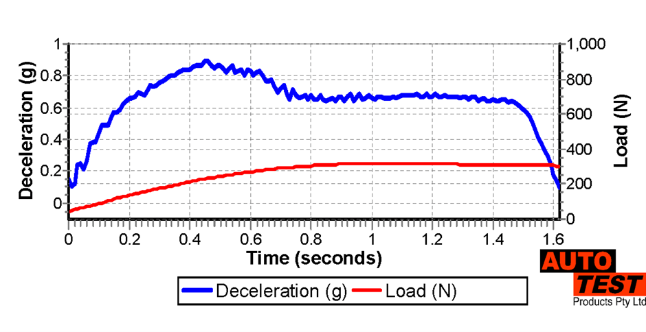
Similarly, there is a general lack of understanding of the actual braking cycle and what in fact occurred over the time-period between the application of the brakes and the vehicle coming to a stop. Below is shown a typical plot from the Autotest manufactured Portable Brake Testing Unit, which prints out a graph calculated from samples taken every 100/second of the deceleration achieved between the time the brakes are applied and the vehicle comes to a halt. It is possible to see several aspects of the braking cycle described in this plot and it helps to understand the actual braking process and more clearly defines the peak acceleration and the sustained deceleration.
The following points are identifiable from the graph below. The graph is created from an AutoTest® Heavy portable brake tester.

A Victorian based manufacturer, AutoTest® Products, is taking an innovative approach to testing equipment to ensure a brake’s capabilities and operating performance are factored into the safety of a vehicle.
AutoTest® provides a range of state-of-the-art automotive testing and diagnostic products, designed to improve the accuracy of the test results used to meet safety regulations. AutoTest® products will also help generate business for workshops with or without Licensed Vehicle Testers (LVT) status.
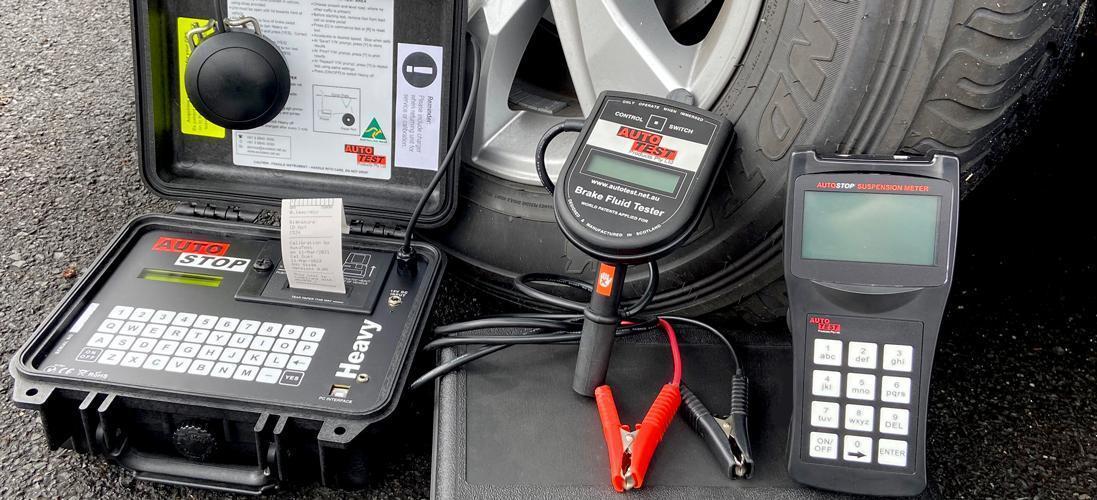
Offering product lines to cover all corners of the brake triangle; brake friction material, Brake Fluid, and suspension.
AutoTest® supplies workshops, regulatory authorities, and service testing stations across the world, including Australia, New Zealand, USA, UK, South Africa, Malaysia, Holland, France, and Germany, with products from the AutoStop range. AutoStop® Maxi brake meter is used by over 3000 workshops in New South Wales alone!

AutoStop® Heavy brake tester is a portable, battery-powered, in-vehicle brake performance tester that measures average and maximum acceleration, stopping distance, test speed, and pedal-force required to stop a vehicle. It evaluates brake performance in a quick reliable manner, printing an accurate test report that complies with International Standards. An efficient diagnostic and compliance tool, designed to test service and emergency brakes of heavy and slow-moving vehicles, off-road vehicles, and even forklifts used in the transport and mining industries, it complies with all the current regulations including the most recent amendment to ISO 3450.
Alternatively, for testing brakes on Light Vehicles, we offer the AutoStop® Maxi brake meter.
The AutoTest® Brake Fluid Tester efficiently and accurately measures the moisture content in vehicle brake fluid. This user-friendly tester helps to prevent vapour lock and corrosion of engine parts. It provides accurate results in less than one minute that allows dealers to identify vehicles that require a brake fluid change. The Brake Fluid Tester also increases the effectiveness of quick lube inspections, seasonal brake checks and routine servicing.
AutoStop® Suspension Meter determines the vertical suspension movement, measuring damping coefficient and counting number of rebounds. It is compatible with most vehicle types and can be used on both stationary and moving vehicles.
Keep your workshop and equipment updated!
Subscribe to our newsletter for exclusive sales, discounts, and the latest news.
Sign up today!